

What Does Usb Micro Data Cable Look Like
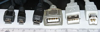
Various USB connectors forth a centimeter ruler for scale. From left to right:
- Micro-B plug
- eight-pin Mini-B plug, a proprietary connector used on many older Japanese cameras for both USB and analog AV output (This strongly resembles the viii-pivot Micro-B plug which often has only 5 pin positions occupied.)
- Mini-B plug
- Blazon-A receptacle (inverted, so the contacts are visible)
- Type-A plug
- Type-B plug
The initial versions of the USB standard specified connectors that were like shooting fish in a barrel to use and that would have acceptable life spans; revisions of the standard added smaller connectors useful for compact portable devices. College-speed evolution of the USB standard gave rise to another family unit of connectors to permit additional data paths. All versions of USB specify cable backdrop; version iii.10 cables include additional information paths. The USB standard included ability supply to peripheral devices; modernistic versions of the standard extend the ability commitment limits for battery charging and devices requiring up to 100 watts. USB has been selected as the standard charging format for many mobile phones, reducing the proliferation of proprietary chargers.
Connectors [edit]

Comparing of USB connector plugs, excluding USB-C blazon plugs
The three sizes of USB connectors are the default or standard format intended for desktop or portable equipment, the mini intended for mobile equipment, which was deprecated when it was replaced by the thinner micro size, all of which were deprecated with the release of Type-C. There are five speeds for USB data transfer: Low Speed, Total Speed, Loftier Speed (from version 2.0 of the specification), SuperSpeed (from version 3.0), and SuperSpeed+ (from version 3.1). The modes take differing hardware and cabling requirements. USB devices accept some choice of implemented modes, and USB version is not a reliable statement of implemented modes. Modes are identified past their names and icons, and the specification suggests that plugs and receptacles be colour-coded (SuperSpeed is identified by blue).
Unlike other information buses (such as Ethernet), USB connections are directed; a host device has "downstream" facing ports that connect to the "upstream" facing ports of devices. Only downstream facing ports provide power; this topology was chosen to easily prevent electrical overloads and damaged equipment. Thus, USB cables take different ends: A and B, with unlike physical connectors for each. Each format has a plug and receptacle divers for each of the A and B ends. A USB cable, by definition, has a plug on each stop—i A (or C) and one B (or C)—and the respective receptacle is usually on a computer or electronic device. The mini and micro formats may connect to an AB receptacle, which accepts either an A or a B plug, that plug determining the behavior of the receptacle.
Connector properties [edit]
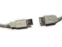
USB extension cable, plug on the left, receptacle (nonstandard, receptacles normally non allowed on cables) on the right
The connectors the USB committee specifies back up a number of USB'southward underlying goals, and reverberate lessons learned from the many connectors the computer industry has used. The connector mounted on the host or device is called the receptacle, and the connector attached to the cable is called the plug.[1] The official USB specification documents as well periodically define the term male person to represent the plug, and female person to stand for the receptacle, those these uses are inconsistent with established definitions of connector gender.[ii]
By pattern, it is difficult to insert a USB plug into its receptacle incorrectly. The USB specification requires that the cable plug and receptacle be marked so the user tin recognize the proper orientation.[i] The USB-C plug notwithstanding is reversible. USB cables and small-scale USB devices are held in identify by the gripping strength from the receptacle, with no screws, clips, or thumb-turns every bit other connectors use.
The different A and B plugs forestall accidentally connecting two power sources. Withal, some of this directed topology is lost with the advent of multi-purpose USB connections (such as USB On-The-Go in smartphones, and USB-powered Wi-Fi routers), which require A-to-A, B-to-B, and sometimes Y/splitter cables. See the USB On-The-Go connectors section below for a more than detailed summary description.
In that location are so-chosen cables with A plugs on both ends, which may be valid if the "cable" includes, for example, a USB host-to-host transfer device with two ports.[iii] This is, by definition, a device with two logical B ports, each with a captive cable, non a cable with two A ends.
Durability [edit]
The standard connectors were designed to exist more robust than many past connectors. This is because USB is hot-swappable, and the connectors would exist used more frequently, and perhaps with less care, than previous connectors.
Standard USB has a minimum rated lifetime of 1,500 cycles of insertion and removal,[4] the mini-USB receptacle increases this to 5,000 cycles,[iv] and the newer Micro-USB[4] and USB-C receptacles are both designed for a minimum rated lifetime of x,000 cycles of insertion and removal.[5] To accomplish this, a locking device was added and the foliage-leap was moved from the jack to the plug, so that the about-stressed role is on the cable side of the connection. This change was made so that the connector on the less expensive cable would acquit the most wear.[half-dozen] [4]
In standard USB, the electrical contacts in a USB connector are protected by an next plastic natural language, and the entire connecting assembly is commonly protected by an enclosing metallic shell.[4]
The trounce on the plug makes contact with the receptacle before whatsoever of the internal pins. The beat out is typically grounded, to misemploy static electricity and to shield the wires within the connector.
Compatibility [edit]
The USB standard specifies tolerances for compliant USB connectors to minimize concrete incompatibilities in connectors from different vendors. The USB specification also defines limits to the size of a connecting device in the surface area around its plug, so that adjacent ports are non blocked. Compliant devices must either fit within the size restrictions or support a compliant extension cable that does.
Pinouts [edit]
USB 2.0 uses two wires for power (VPassenger vehicle and GND), and two for differential serial data signals. Mini and micro connectors accept their GND connections moved from pin #iv to pin #5, while their pin #4 serves as an ID pin for the On-The-Go host/client identification.[seven]
USB 3.0 provides two additional differential pairs (four wires, SSTx+, SSTx−, SSRx+ and SSRx−), providing full-duplex data transfers at SuperSpeed, which makes it similar to Serial ATA or single-lane PCI Express.

Standard, Mini-, and Micro-USB plugs shown end-on, not to calibration. Calorie-free areas represent cavities. The plugs are pictured with USB logo to the height.[8]
Micro-B SuperSpeed plug
- Ability (VBUS, 5 V)
- Information− (D−)
- Data+ (D+)
- ID (On-The-Get)
- GND
- SuperSpeed transmit− (SSTx−)
- SuperSpeed transmit+ (SSTx+)
- GND
- SuperSpeed receive− (SSRx−)
- SuperSpeed receive+ (SSRx+)
| Pin | Name | Wire color[a] | Clarification | |
|---|---|---|---|---|
| ane | 5Motorbus | Red or | Orange | +5 5 |
| 2 | D− | White or | Gold | Data− |
| 3 | D+ | Dark-green | Information+ | |
| 4 | GND | Black or | Bluish | Ground |
| Pivot | Name | Wire color[a] | Description |
|---|---|---|---|
| one | VDouble-decker | Red | +5 V |
| 2 | D− | White | Information− |
| 3 | D+ | Dark-green | Data+ |
| 4 | ID | No wire | On-The-Get ID distinguishes cable ends:
|
| 5 | GND | Black | Signal footing |
- ^ a b In some sources D+ and D− are erroneously swapped.
Colors [edit]

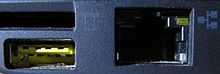
A yellow charge-only USB port on a front panel USB iii.0 switch with card reader

A blue Standard-A USB connector on a Sagemcom F@ST 3864OP ADSL modem router without USB 3.0 contacts fitted
| Color | Location | Description | ||||||
|---|---|---|---|---|---|---|---|---|
| Blackness or white | Ports and plugs | Blazon-A or type-B | ||||||
| Blue (Pantone 300C) | Ports and plugs | Type-A or type-B, SuperSpeed | ||||||
| Teal blueish | Ports and plugs | Type-A or type-B, SuperSpeed+ | ||||||
| Green | Ports and plugs | Type-A or type-B, Qualcomm Quick Charge (QC)[9] | ||||||
| Purple | Plugs only | Type-A or USB-C, Huawei SuperCharge | ||||||
| Yellowish or red | Ports only | High-current or slumber-and-charge | ||||||
| Orangish | Ports only | High-memory connector, mostly used on industrial hardware | ||||||
USB ports and connectors are often color-coded to distinguish their different functions and USB versions. These colors are non function of the USB specification and can vary between manufacturers; for case, USB three.0 specification mandates advisable color-coding while information technology only recommends blue inserts for standard-A USB iii.0 connectors and plugs.[10]
Connector types [edit]
USB connector types multiplied as the specification progressed. The original USB specification detailed standard-A and standard-B plugs and receptacles. The connectors were different and so that users could not connect i computer receptacle to another. The data pins in the standard plugs are recessed compared to the power pins so that the device can power up before establishing a data connection. Some devices operate in different modes depending on whether the data connection is made. Charging docks supply power and do non include a host device or data pins, assuasive any capable USB device to accuse or operate from a standard USB cablevision. Charging cables provide power connections, only not data. In a charge-only cablevision, the data wires are shorted at the device end, otherwise, the device may refuse the charger as unsuitable.
Standard connectors [edit]

Pin configuration of blazon-A and blazon-B plugs viewed end-on
- The type-A plug. This plug has an elongated rectangular cross-section, inserts into a type-A receptacle on a downstream port on a USB host or hub, and carries both power and data. Convict cables on USB devices, such as keyboards or mice, finish with a type-A plug.
- The type-B plug: This plug has a most square cross-section with the top exterior corners askew. As part of a removable cable, it inserts into an upstream port on a device, such as a printer. On some devices, the type-B receptacle has no data connections, beingness used solely for accepting power from the upstream device. This 2-connector-type scheme (A/B) prevents a user from accidentally creating a loop.[11] [12]
The maximum immune cantankerous-section of the overmold kicking (which is part of the connector used for its treatment) is 16 by 8 mm (0.63 by 0.31 in) for the standard-A plug type, while for the type-B information technology is 11.5 by 10.v mm (0.45 by 0.41 in).[2]
Mini connectors [edit]
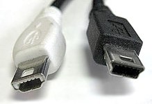
Mini-A (left) and Mini-B (right) plugs
Mini-USB connectors were introduced together with USB two.0 in Apr 2000, for use with smaller devices such every bit digital cameras, smartphones, and tablet computers. The Mini-A connector and the Mini-AB receptacle connector have been deprecated since May 2007.[13] Mini-B connectors are still supported, but are not On-The-Get-compliant;[14] the Mini-B USB connector was standard for transferring data to and from the early smartphones and PDAs. Both Mini-A and Mini-B plugs are approximately 3 past 7 mm (0.12 past 0.28 in).
Micro connectors [edit]

Micro-A plug

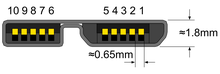
Micro-B plug
Micro-USB connectors, which were announced past the USB-IF on four January 2007,[15] [sixteen] have a similar width to Mini-USB, only approximately half the thickness, enabling their integration into thinner portable devices. The Micro-A connector is 6.85 by 1.8 mm (0.270 by 0.071 in) with a maximum overmold boot size of 11.vii past 8.5 mm (0.46 by 0.33 in), while the Micro-B connector is half dozen.85 by 1.viii mm (0.270 by 0.071 in) with a maximum overmold size of ten.half-dozen by 8.5 mm (0.42 by 0.33 in).[8]
The thinner Micro-USB connectors were intended to replace the Mini connectors in devices manufactured since May 2007, including smartphones, personal digital administration, and cameras.[17]
The Micro plug blueprint is rated for at least 10,000 connect-disconnect cycles, which is more than the Mini plug design.[xv] [18] The Micro connector is besides designed to reduce the mechanical wear on the device; instead, the easier-to-replace cablevision is designed to bear the mechanical clothing of connectedness and disconnection. The Universal Series Omnibus Micro-USB Cables and Connectors Specification details the mechanical characteristics of Micro-A plugs, Micro-AB receptacles (which take both Micro-A and Micro-B plugs), Double-Sided Micro USB, and Micro-B plugs and receptacles,[18] along with a Standard-A receptacle to a Micro-A plug adapter.
OMTP standard [edit]
Micro-USB was endorsed as the standard connector for data and power on mobile devices by the cellular phone carrier group Open Mobile Terminal Platform (OMTP) in 2007.[19]
Micro-USB was embraced equally the "Universal Charging Solution" past the International Telecommunication Wedlock (ITU) in October 2009.[twenty]
In Europe, micro-USB became the defined common external ability supply (EPS) for use with smartphones sold in the European union,[21] and 14 of the earth'due south largest mobile phone manufacturers signed the EU'south common EPS Memorandum of Understanding (MoU).[22] [23] Apple, i of the original MoU signers, makes Micro-USB adapters available—as permitted in the Mutual EPS MoU—for its iPhones equipped with Apple'due south proprietary 30-pin dock connector or (later) Lightning connector.[24] [25] according to the CEN, CENELEC, and ETSI.
USB 3.ten connectors and astern compatibility [edit]
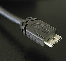
USB 3.0 Micro-B SuperSpeed plug
USB iii.0 introduced Type-A SuperSpeed plugs and receptacles as well as micro-sized Blazon-B SuperSpeed plugs and receptacles. The 3.0 receptacles are backward-compatible with the corresponding pre-3.0 plugs.
USB three.x and USB 1.ten Type-A plugs and receptacles are designed to interoperate. To accomplish USB three.0'due south SuperSpeed (and SuperSpeed+ for USB 3.1 Gen 2), 5 extra pins are added to the unused surface area of the original 4 pin USB 1.0 design, making USB 3.0 Type-A plugs and receptacles backward compatible to those of USB i.0.
On the device side, a modified Micro-B plug (Micro-B SuperSpeed) is used to cater for the v boosted pins required to achieve the USB 3.0 features (USB-C plug can besides be used). The USB 3.0 Micro-B plug finer consists of a standard USB two.0 Micro-B cablevision plug, with an additional v pins plug "stacked" to the side of it. In this fashion, cables with smaller five pin USB two.0 Micro-B plugs tin be plugged into devices with 10 contact USB three.0 Micro-B receptacles and achieve backward compatibility.
USB cables exist with various combinations of plugs on each stop of the cable, equally displayed below in the USB cables matrix.

USB On-The-Go connectors [edit]
USB On-The-Go (OTG) introduces the concept of a device performing both master and slave roles. All electric current OTG devices are required to take i, and only one, USB connector: a Micro-AB receptacle. (In the past, before the development of Micro-USB, On-The-Go devices used Mini-AB receptacles).
The Micro-AB receptacle is capable of accepting both Micro-A and Micro-B plugs, attached to any of the legal cables and adapters as defined in revision ane.01 of the Micro-USB specification.
To enable Type-AB receptacles to distinguish which stop of a cable is plugged in, plugs have an "ID" pin in addition to the four contacts in standard-size USB connectors. This ID pin is connected to GND in Type-A plugs, and left unconnected in Type-B plugs. Typically, a pull-up resistor in the device is used to observe the presence or absenteeism of an ID connection.
The OTG device with the A-plug inserted is called the A-device and is responsible for powering the USB interface when required, and by default assumes the role of host. The OTG device with the B-plug inserted is chosen the B-device and by default assumes the office of peripheral. An OTG device with no plug inserted defaults to acting as a B-device. If an awarding on the B-device requires the role of host, and so the Host Negotiation Protocol (HNP) is used to temporarily transfer the host role to the B-device.
OTG devices attached either to a peripheral-only B-device or a standard/embedded host have their role fixed past the cable, since in these scenarios information technology is only possible to adhere the cable one manner.[ commendation needed ]
USB-C [edit]
![]()

USB cable with a USB-C plug and a USB-C port on a laptop
Developed at roughly the same fourth dimension every bit the USB 3.1 specification, but distinct from it, the USB-C Specification 1.0 was finalized in August 2014[26] and defines a new small reversible-plug connector for USB devices.[27] The USB-C plug connects to both hosts and devices, replacing diverse Blazon-A and Blazon-B connectors and cables with a standard meant to exist future-proof.[26] [28]
The 24-pin double-sided connector provides 4 power–basis pairs, two differential pairs for USB 2.0 data (though only one pair is implemented in a USB-C cable), 4 pairs for SuperSpeed data bus (simply two pairs are used in USB 3.1 mode), two "sideband utilize" pins, 5CONN +five V power for active cables, and a configuration pivot for cable orientation detection and dedicated biphase mark code (BMC) configuration data aqueduct.[29] [30] Blazon-A and Type-B adaptors and cables are required for older hosts and devices to plug into USB-C hosts and devices. Adapters and cables with a USB-C receptacle are not allowed.[31]
Total-featured USB-C 3.1 cables are electronically marked cables that comprise a full set of wires and a chip with an ID role based on the configuration data channel and vendor-defined messages (VDMs) from the USB Ability Delivery 2.0 specification. USB-C devices also support power currents of 1.5 A and iii.0 A over the five V power omnibus in addition to baseline 900 mA; devices can either negotiate increased USB current through the configuration line or they can support the full Power Delivery specification using both BMC-coded configuration line and legacy BFSK-coded FiveCharabanc line.[ citation needed ]
Host and device interface receptacles [edit]
USB plugs fit one receptacle with notable exceptions for USB On-The-Get "AB" support and the general backward compatibility of USB 3.0 as shown.
| Plug Receptacle | USB A | USB 3.0 A SS | USB B | USB 3.0 B SS | USB Mini-A | USB Mini-B | USB Micro-A1  | USB Micro-B | USB three.0 Micro-B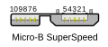 | USB-C |
|---|---|---|---|---|---|---|---|---|---|---|
USB A | Yes | Simply non- SuperSpeed | No | No | No | No | No | No | No | No |
USB 3.0 A SS | Merely non- SuperSpeed | Yes | No | No | No | No | No | No | No | No |
USB B | No | No | Yes | No | No | No | No | No | No | No |
USB iii.0 B SS | No | No | Merely non- SuperSpeed | Yeah | No | No | No | No | No | No |
| USB Mini-A | No | No | No | No | Deprecated | No | No | No | No | No |
| USB Mini-AB | No | No | No | No | Deprecated | Deprecated | No | No | No | No |
| USB Mini-B | No | No | No | No | No | Aye | No | No | No | No |
| USB Micro-AB | No | No | No | No | No | No | Yeah | Yes | No | No |
| USB Micro-B | No | No | No | No | No | No | No | Yes | No | No |
| USB 3.0 Micro-B SS | No | No | No | No | No | No | No | Only not- SuperSpeed | Yes | No |
| USB-C | No | No | No | No | No | No | No | No | No | Yep |
| ^1 No corresponding Micro-A receptacle was ever designed. | ||||||||||
| Plugs, each terminate | USB A | USB Mini-A | USB Micro-A | USB B | USB Mini-B | USB Micro-B | USB 3.0 Micro-B | USB-C |
|---|---|---|---|---|---|---|---|---|
| USB A | Proprietary, chancy | Proprietary, hazardous | Proprietary, chancy | Yes | Yes | Aye | Yes | Yes |
| USB Mini-A | No | No | Deprecated | Deprecated | Non- standard | No | No | |
| USB Micro-A | No | Non- standard | Non- standard | Aye | No | No | ||
| USB B | No | No | No | No | Yep | |||
| USB Mini-B | OTG not- standard | OTG non- standard | No | Yes | ||||
| USB Micro-B | OTG non- standard | No | Yes | |||||
| USB 3.0 Micro-B | OTG non- standard | Yep | ||||||
| USB-C | Aye |
- Proprietary, hazardous
- Existing for specific proprietary purposes, not inter-operable with USB-IF compliant equipment and peradventure damaging to both devices when plugged in. In addition to the above cablevision assemblies comprising two plugs, an "adapter" cablevision with a Micro-A plug and a standard-A receptacle is compliant with USB specifications.[8] Other combinations of connectors are non compliant.In that location do exist A-to-A assemblies, referred to every bit cables (such every bit the Like shooting fish in a barrel Transfer Cable); however, these have a pair of USB devices in the eye, making them more than just cables.
- Not-standard
- The USB standards do non exhaustively list all combinations with one A-type and one B-type connector, however, most such cables accept good chances of working.
- OTG non-standard
- Commonly available "OTG" cables that address widespread misuse of Micro-B and Mini-B receptacles for OTG devices, e.g. smartphones (every bit opposed to Micro-AB and Mini-AB, which accept either plug.) While not compliant with the USB standards, these cables at least do not provide a device damage hazard since B-blazon ports on devices are unpowered by default.[32]
- Deprecated
- Some older devices and cables with Mini-A connectors accept been certified by USB-IF. The Mini-A connector is obsolete: no new Mini-A connectors and neither Mini-A nor Mini-AB receptacles volition be certified.[13]Notation: Mini-B is not deprecated, although information technology is less and less used since the arrival of Micro-B. Micro-B is non the same every bit USB type B. Micro-B has one more wire than USB type B.
Proprietary connectors and formats [edit]
Manufacturers of personal electronic devices might non include a USB standard connector on their product for technical or marketing reasons.[33] Some manufacturers such as Apple provide proprietary cables that permit their devices to physically connect to a USB standard port. Total functionality of proprietary ports and cables with USB standard ports is not bodacious; for case, some devices only utilize the USB connection for battery charging and do not implement whatever data transfer functions.[34]
Cabling [edit]
![]()
A USB twisted pair, in which the Data+ and Data− conductors are twisted together in a double helix. The wires are enclosed in a further layer of shielding.
The D± signals used by low, full, and high speed are carried over a twisted pair (typically unshielded) to reduce noise and crosstalk. SuperSpeed uses separate transmit and receive differential pairs, which additionally require shielding (typically, shielded twisted pair but twinax is also mentioned by the specification). Thus, to support SuperSpeed data transmission, cables incorporate twice as many wires and are thus larger in diameter.[35]
The USB 1.ane standard specifies that a standard cable can take a maximum length of v meters (16 ft five in) with devices operating at full speed (12 Mbit/s), and a maximum length of iii meters (9 ft ten in) with devices operating at low speed (1.five Mbit/s).[36] [37] [38]
USB ii.0 provides for a maximum cable length of five meters (16 ft 5 in) for devices running at loftier speed (480 Mbit/southward). The master reason for this limit is the maximum allowed circular-trip filibuster of nigh one.v μs. If USB host commands are unanswered by the USB device within the immune time, the host considers the command lost. When calculation USB device response time, delays from the maximum number of hubs added to the delays from connecting cables, the maximum acceptable filibuster per cable amounts to 26 ns.[39] The USB 2.0 specification requires that cablevision delay exist less than 5.2 ns/m (1.six ns/ft), ( 192000 km/south)—which is close to the maximum achievable transmission speed for standard copper wire.
The USB 3.0 standard does not directly specify a maximum cablevision length, requiring merely that all cables meet an electrical specification: for copper cabling with AWG 26 wires the maximum practical length is 3 meters (9 ft 10 in).[twoscore]
Power [edit]
Upstream USB connectors supply power at a nominal 5 V DC via the V_BUS pin to downstream USB devices.
Voltage tolerance and limits [edit]

Worst-case voltage drop topology of a USB ii.0 host to depression-power device concatenation, at steady state
The tolerance on V_BUS at an upstream (or host) connector was originally ±5% (ie. could lie anywhere in the range 4.75 V to v.25 Five). With the release of the USB Type-C specification in 2014 and its 3 A ability capability, the USB-IF elected to increase the upper voltage limit to v.5 V to combat voltage droop at higher currents.[41] The USB 2.0 specification (and therefore implicitly also the USB 3.x specifications) was likewise updated to reverberate this change at that time.[42] A number of extensions to the USB Specifications have progressively farther increased the maximum commanded V_BUS voltage: starting with 6.0V with USB BC 1.2,[43] to 21.five V with USB PD 2.0[44] and 50.nine V with USB PD iii.1,[44] while still maintaining backwards compatibility with USB 2.0 by requiring various forms of handshake before increasing the nominal voltage above 5 V.
USB PD continues the use of the bilateral 5% tolerance, with allowable voltages of PDO ±5% ±0.5 V (eg. for a PDO of 9.0 V, the maximum and minimum limits are 9.95 V and 8.05 5, respectively).[44]
There are several minimum commanded voltages defined at different locations within a chain of connectors, hubs, and cables between an upstream host (providing the power) and a downstream device (consuming the ability). To allow for voltage drops, the voltage at the host port, hub port, and device are specified to exist at least 4.75 5, 4.4 V, and 4.35 V respectively by USB ii.0 for low-power devices[a], but must be at to the lowest degree 4.75 Five at all locations for high-power[b] devices (however, high-ability devices are required to operate as a low-powered device so that they may be detected and enumerated if connected to a low-power upstream port). The USB 3.10 specifications require that all devices must operate downwardly to 4.00 V at the device port.
Different USB 2.0 and USB 3.2, USB4 does not ascertain its ain VBUS-based power model. Power for USB4 operation is established and managed equally divers in the USB Type-C Specification and the USB PD Specification.
- ^ Low-power devices are those which draw less than 1 unit load. 1 unit load is 100 mA for USB 2.0
- ^ Loftier-power devices in USB 2.0 are those draw more than than ane unit load (up to a maximum of 5 unit of measurement loads). one unit load is 100mA.

Worst-case voltage drop topology of a USB 3.ten host to device concatenation, at steady state. Notation that under transient conditions the supply at the device tin can momentarily drop from 4.0 V to 3.67 Five.
Allowable current draw [edit]
| Specification | Current | Voltage | Power (max.) |
|---|---|---|---|
| Low-ability device | 100 mA | 5 5 | 0.50 W |
| Depression-power SuperSpeed (USB 3.0) device | 150 mA | 5 5 | 0.75 Due west |
| High-power device | 500 mA[a] | five V | two.v W |
| Loftier-ability SuperSpeed (USB 3.0) device | 900 mA[b] | 5 V | 4.5 West |
| Multi-lane SuperSpeed (USB 3.2 Gen x2) device | 1.5 A[c] | v 5 | 7.five Due west |
| Battery Charging (BC) 1.ii | 1.5 A | 5 V | 7.5 W |
| USB-C | 1.5 A | 5 V | 7.5 Westward |
| 3 A | 5 V | fifteen Westward | |
| Power Delivery 1.0/2.0/3.0 Type-C | 5 A[d] | 20 5 | 100 W |
| Power Delivery iii.1 Type-C | v A[d] | 48 V[east] | 240 W |
| |||
The limit to device power draw is stated in terms of a unit load which is 100 mA for USB two.0, or 150 mA for SuperSpeed (ie USB 3.x) devices. Low-power devices may draw at most 1 unit load, and all devices must deed equally low-power devices earlier they are configured. A high-powered device must be configured, after which it may describe up to 5 unit loads (500 mA), or 6 unit of measurement loads (900 mA) for SuperSpeed devices, every bit specified in its configuration because the maximum power may not always be available from the upstream port.[45] [46] [47] [48]
A bus-powered hub is a high-ability device providing low-power ports. Information technology draws 1 unit load for the hub controller and 1 unit load for each of at most 4 ports. The hub may besides have some not-removable functions in place of ports. A self-powered hub is a device that provides high-power ports by supplementing the ability supply from the host with its ain external supply. Optionally, the hub controller may draw power for its operation every bit a depression-power device, just all high-power ports must describe from the hub'south self-power.
Where devices (for example, high-speed disk drives) require more power than a loftier-ability device can depict,[49] they part erratically, if at all, from bus ability of a single port. USB provides for these devices as being self-powered. However, such devices may come with a Y-shaped cablevision that has 2 USB plugs (1 for power and data, the other for only power), so as to draw power as 2 devices.[fifty] Such a cable is non-standard, with the USB compliance specification stating that "use of a 'Y' cable (a cable with two A-plugs) is prohibited on any USB peripheral", meaning that "if a USB peripheral requires more than power than allowed past the USB specification to which it is designed, then information technology must be self-powered."[51]
USB battery charging [edit]
USB Battery Charging (BC) defines a charging port, which may exist a charging downstream port (CDP), with data, or a dedicated charging port (DCP) without information. Dedicated charging ports can be plant on USB ability adapters to run attached devices and battery packs. Charging ports on a host with both kinds will exist labelled.[52]
The charging device identifies a charging port past non-information signaling on the D+ and D− terminals. A dedicated charging port places a resistance not exceeding 200 Ω across the D+ and D− terminals.[52] : § 1.4.7; table 5-3
Per the base specification, any device attached to a standard downstream port (SDP) must initially be a low-power device, with high-power mode contingent on later USB configuration by the host. Charging ports, however, can immediately supply betwixt 0.5 and 1.five A of electric current. The charging port must non use electric current limiting beneath 0.5 A, and must not shut downwards below 1.5 A or earlier the voltage drops to ii V.[52]
Since these currents are larger than in the original standard, the extra voltage drop in the cable reduces noise margins, causing problems with High Speed signaling. Bombardment Charging Specification i.1 specifies that charging devices must dynamically limit motorbus power electric current describe during High Speed signaling;[53] ane.2 specifies that charging devices and ports must exist designed to tolerate the higher ground voltage difference in High Speed signaling.
Revision 1.2 of the specification was released in 2010. It made several changes, and increased limits including allowing i.five A on charging downstream ports for unconfigured devices—allowing High Speed advice while having a current upward to 1.five A. Likewise, support was removed for charging port detection via resistive mechanisms.[54]
Before the Battery Charging Specification was divers, in that location was no standardized way for the portable device to enquire how much current was available. For case, Apple tree's iPod and iPhone chargers indicate the available current by voltages on the D− and D+ lines. When D+ = D− = two.0 V, the device may pull up to 900 mA. When D+ = two.0 V and D− = 2.8 V, the device may pull up to 1 A of current.[55] When D+ = ii.eight V and D− = 2.0 5, the device may pull upward to ii A of current.[56]
Accessory charging adaptors (ACA) [edit]
Portable devices having a USB On-The-Get port may desire to charge and access a USB peripheral simultaneously, yet having only a single port (both due to On-The-Get and space requirement) prevents this. Accompaniment charging adapters (ACA) are devices that provide portable charging ability to an On-The-Go connection between host and peripheral.
ACAs have three ports: the OTG port for the portable device, which is required to have a Micro-A plug on a captive cable; the accompaniment port, which is required to accept a Micro-AB or type-A receptacle; and the charging port, which is required to accept a Micro-B receptacle, or blazon-A plug or charger on a convict cable. The ID pin of the OTG port is not connected within plug as usual, but to the ACA itself, where signals outside the OTG floating and footing states are used for ACA detection and country signaling. The charging port does not pass data, but does utilize the D± signals for charging port detection. The accessory port acts as any other port. When accordingly signaled by the ACA, the portable device can charge from the double-decker power as if there were a charging port present; any OTG signals over jitney ability are instead passed to the portable device via the ID signal. Passenger vehicle ability is also provided to the accessory port from the charging port transparently.[52]
USB Power Delivery [edit]
![]()
The USB Type-C Charging logo (USB4 20Gbps port)
| Contour | +5 V | +12 V | +xx V |
|---|---|---|---|
| 0 | Reserved | ||
| one | ii.0 A, x W[a] | N/A | N/A |
| 2 | one.5 A, 18 W | ||
| 3 | 3.0 A, 36 W | ||
| 4 | 3.0 A, sixty W | ||
| 5 | 5.0 A, 60 W | 5.0 A, 100 W | |
| |||
| Source output power rating (Due west) | Current, at: (A) | |||||||
|---|---|---|---|---|---|---|---|---|
| +v V | +ix 5 | +xv V | +twenty 5 | +28 V[a] | +36 V[a] | +48 V[a] | ||
| Standard Ability Range (SPR)[58] [59] [60] | 0.5–xv | 0.1–three.0 | N/A | N/A | N/A | N/A | North/A | North/A |
| 15–27 | 3.0 (xv Due west) | ane.67–3.0 | ||||||
| 27–45 | three.0 (27 Due west) | 1.8–3.0 | ||||||
| 45–60 | iii.0 (45 W) | 2.25–3.0 | ||||||
| 60–100 | iii.0–5.0[b] | |||||||
| Extended Power Range (EPR)[60] | 100-140 | iii.0 (60 Westward), five.0 (100 Due west)[b] | iii.57–5.0 | |||||
| 140–180 | 5.0 (140 W) | 3.89–5.0 | ||||||
| 180–240 | 5.0 (180 Due west) | 3.75–5.0 | ||||||
| ||||||||

Power rule of USB Power Commitment Revision iii.0, Version 1.2
In July 2012, the USB Promoters Group announced the finalization of the USB Power Delivery (USB-PD) specification (USB PD rev. 1), an extension that specifies using certified PD enlightened (USB A and USB B plugs have a mechanical marker while Micro plugs have a resistor or capacitor attached to the ID pin indicating the cable capability) USB cables with standard USB Blazon-A and Type-B connectors to deliver increased power (more than than seven.v West) to devices with greater power demands. Devices tin asking college currents and supply voltages from compliant hosts—upwards to two A at five V (for a power consumption of up to 10 W), and optionally up to 3 A or 5 A at either 12 5 (36 W or lx W) or xx Five (60 W or 100 Westward).[61] In all cases, both host-to-device and device-to-host configurations are supported.[62]
The intent is to permit uniformly charging laptops, tablets, USB-powered disks and similarly higher-power consumer electronics, as a natural extension of existing European and Chinese mobile telephone charging standards. This may also affect the way electrical power used for small devices is transmitted and used in both residential and public buildings.[63] [64] The standard is designed to coexist with the previous USB Bombardment Charging specification.[65]
The first Power Delivery specification defined vi fixed power profiles for the power sources. PD-aware devices implement a flexible power management scheme by interfacing with the ability source through a bidirectional data channel and requesting a certain level of electrical power, variable up to 5 A and 20 Five depending on supported profile. The power configuration protocol can use BMC coding over the CC wire if one is nowadays, or a 24 MHz BFSK-coded manual channel on the VBUS line.
The USB Power Commitment specification revision 2.0 (USB PD Rev. two.0) has been released as part of the USB iii.i suite.[58] [66] [67] It covers the USB-C cablevision and connector with a dissever configuration aqueduct, which now hosts a DC coupled low-frequency BMC-coded information channel that reduces the possibilities for RF interference.[68] Power Delivery protocols take been updated to facilitate USB-C features such as cablevision ID function, Alternate Mode negotiation, increased 5BUS currents, and VCONN-powered accessories.
As of USB Power Delivery specification revision ii.0, version i.2, the vi fixed power profiles for power sources have been deprecated.[69] USB PD Power Rules replace power profiles, defining four normative voltage levels at 5 Five, 9 5, fifteen V, and 20 Five. Instead of vi stock-still profiles, power supplies may support whatever maximum source output ability from 0.five W to 100 W.
The USB Power Delivery specification revision three.0 defines an optional Programmable Power Supply (PPS) protocol that allows granular control over VCoach power, allowing a range of iii.three to 21 5 in xx mV steps to facilitate constant-current or constant-voltage charging. Revision 3.0 also adds extended configuration messages and fast role swap and deprecates the BFSK protocol.[59] [seventy] [71]
Every bit of April 2016,[update] there are silicon controllers available from several sources such equally Texas Instruments and Cypress Semiconductor.[72] [73] Power supplies bundled with USB-C based laptops back up USB PD.[74] In addition accessories are available that back up USB PD Rev. 2.0 at multiple voltages.[75] [76] [77] [78]
![]()
The Certified USB Fast Charger logo for USB Type-C charging ports
On 8 Jan 2018 USB-IF announced "Certified USB Fast Charger" logo for chargers that use "Programmable Power Supply" (PPS) protocol from the USB Power Delivery 3.0 specification.[79]
In May 2021, the USB PD promoter grouping launched revision iii.1 of the specification.[threescore] Revision 3.1 adds Extended Ability Range (EPR) mode which allows higher voltages of 28, 36, and 48 V, providing up to 240 Westward of power (48 5 at v A), and the "Adjustable Voltage Supply" (AVS) protocol which allows specifying the voltage from a range of fifteen to 48 V in 100 mV steps.[80] [81] Higher voltages require electronically marked EPR cables that support 5 A operation and incorporate mechanical improvements required by the USB Type-C standard rev. 2.1; existing power modes are retroactively renamed Standard Power Range (SPR). In October 2021 Apple introduced a 140 W (28 5 5 A) GaN USB PD charger with new Macbooks.[82]
Prior to Power Delivery, mobile phone vendors used custom protocols to exceed the 7.5 W cap on USB-BCS. For example, Qualcomm's Quick Charge 2.0 is able to deliver 18 West at a higher voltage, and VOOC delivers xx Westward at the normal five V.[83] Some of these technologies, such as Quick Charge iv, eventually became compatible with USB PD again.[84]
Slumber-and-charge ports [edit]
A yellow USB port denoting slumber-and-accuse
Slumber-and-charge USB ports can be used to charge electronic devices even when the figurer that hosts the ports is switched off. Normally, when a estimator is powered off the USB ports are powered down. This feature has also been implemented on some laptop docking stations assuasive device charging even when no laptop is present.[85] On laptops, charging devices from the USB port when it is not being powered from AC drains the laptop bombardment; well-nigh laptops have a facility to stop charging if their own bombardment charge level gets besides low.[86]
On Dell, HP and Toshiba laptops, sleep-and-charge USB ports are marked with the standard USB symbol with an added lightning bolt or battery icon on the right side.[87] Dell calls this feature PowerShare,[88] and it needs to be enabled in the BIOS. Toshiba calls it USB Slumber-and-Charge.[89] On Acer Inc. and Packard Bell laptops, sleep-and-accuse USB ports are marked with a non-standard symbol (the letters USB over a drawing of a battery); the feature is called Power-off USB.[90] Lenovo calls this characteristic Always On USB.[91]
Mobile device charger standards [edit]
In China [edit]
Every bit of fourteen June 2007[update], all new mobile phones applying for a licence in Red china are required to utilise a USB port as a power port for battery charging.[92] [93] This was the get-go standard to utilize the convention of shorting D+ and D− in the charger.[94]
OMTP/GSMA Universal Charging Solution [edit]
In September 2007, the Open up Mobile Terminal Platform group (a forum of mobile network operators and manufacturers such every bit Nokia, Samsung, Motorola, Sony Ericsson, and LG) announced that its members had agreed on Micro-USB as the time to come mutual connector for mobile devices.[95] [96]
The GSM Clan (GSMA) followed suit on 17 February 2009,[97] [98] [99] [100] and on 22 April 2009, this was farther endorsed past the CTIA – The Wireless Association,[101] with the International Telecommunication Marriage (ITU) announcing on 22 October 2009 that information technology had also embraced the Universal Charging Solution as its "free energy-efficient one-charger-fits-all new mobile telephone solution," and added: "Based on the Micro-USB interface, UCS chargers will also include a 4-star or higher efficiency rating—up to three times more energy-efficient than an unrated charger."[102]
EU smartphone power supply standard [edit]
In June 2009, many of the globe's largest mobile phone manufacturers signed an EC-sponsored Memorandum of Understanding (MoU), agreeing to make almost information-enabled mobile phones marketed in the European union compatible with a common External Power Supply (mutual EPS). The EU's mutual EPS specification (EN 62684:2010) references the USB Battery Charging Specification and is similar to the GSMA/OMTP and Chinese charging solutions.[103] [104] In January 2011, the International Electrotechnical Commission (IEC) released its version of the (EU'southward) common EPS standard as IEC 62684:2011.[105] The European union and its members should adopt a resolution during 2022 for the global adoption of USB Type C chargers for all mobile products on the European market.[106]
Faster-charging standards [edit]
A diversity of (non-USB) standards support charging devices faster than the USB Battery Charging standard. When a device doesn't recognize the faster-charging standard, generally the device and the charger fall back to the USB battery-charging standard of 5 V at 1.five A (vii.v W). When a device detects information technology is plugged into a charger with a uniform faster-charging standard, the device pulls more current or the device tells the charger to increment the voltage or both to increase power (the details vary betwixt standards).[107]
Such standards include:[107]
- Qualcomm Quick Charge (QC)
- MediaTek Pump Express
- Samsung Adaptive Fast Charging
- Oppo Super VOOC Wink Charge, are also known equally Nuance Charge or Warp Charge on OnePlus devices and Dart Charge on Realme devices
- Huawei SuperCharge
- Anker PowerIQ
Non-standard devices [edit]
Some USB devices require more than ability than is permitted past the specifications for a single port. This is common for external difficult and optical disc drives, and mostly for devices with motors or lamps. Such devices can use an external ability supply, which is allowed by the standard, or apply a dual-input USB cable, i input of which is for power and data transfer, the other solely for power, which makes the device a non-standard USB device. Some USB ports and external hubs tin, in practise, supply more than power to USB devices than required past the specification merely a standard-compliant device may non depend on this.
In addition to limiting the total average power used by the device, the USB specification limits the inrush electric current (i.e., the electric current used to charge decoupling and filter capacitors) when the device is beginning connected. Otherwise, connecting a device could cause issues with the host'south internal power. USB devices are also required to automatically enter ultra low-power suspend mode when the USB host is suspended. Nonetheless, many USB host interfaces do not cutting off the power supply to USB devices when they are suspended.[108]
Some non-standard USB devices use the five V power supply without participating in a proper USB network, which negotiates power draw with the host interface. These are usually called USB decorations.[ citation needed ] Examples include USB-powered keyboard lights, fans, mug coolers and heaters, battery chargers, miniature vacuum cleaners, and even miniature lava lamps. In near cases, these items comprise no digital circuitry, and thus are not standard-compliant USB devices. This may cause problems with some computers, such as drawing too much current and damaging circuitry. Prior to the USB Bombardment Charging Specification, the USB specification required that devices connect in a depression-power mode (100 mA maximum) and communicate their electric current requirements to the host, which then permits the device to switch into high-ability style.
Some devices, when plugged into charging ports, draw fifty-fifty more than power (10 watts at ii.one amperes) than the Battery Charging Specification allows—the iPad is one such device;[109] it negotiates the current pull with data pin voltages.[55] Barnes & Noble Nook Colour devices too crave a special charger that runs at 1.nine amperes.[110]
PoweredUSB [edit]
PoweredUSB is a proprietary extension that adds iv pins supplying up to 6 A at 5 5, 12 V, or 24 Five. It is ordinarily used in point of sale systems to power peripherals such as barcode readers, credit card terminals, and printers.
-

The Micro-USB interface is commonly establish on chargers for mobile phones.
-

Australian and New Zealand power receptacle with USB charger receptacle
-
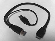
Y-shaped USB 3.0 cable; with such a cable, a device can draw power from ii USB ports simultaneously.
-

A small device that provides voltage and current readouts for devices charged over USB
-

This USB ability meter additionally provides a charge readout (in mAh) and information logging.
-

USB-powered mini fans
-
References [edit]
- ^ a b Universal Serial Bus 3.0 Specification: Revision 1.0. Contributors: Hewlett-Packard, Intel, Microsoft, NEC, ST-Ericsson, Texas Instruments. half-dozen June 2011. p. 531. Archived from the original on 30 December 2013. Retrieved 28 April 2019.
{{cite volume}}: CS1 maint: others (link) - ^ a b "USB two.0 Specification Applied science Change Notice (ECN) #ane: Mini-B connector" (PDF). 20 October 2000. Archived from the original (PDF) on 12 April 2015. Retrieved 28 April 2019 – via www.usb.org.
- ^ "USB connector guide". C2G. Archived from the original on 21 Apr 2014. Retrieved 2 December 2013.
- ^ a b c d e "Universal Serial Bus Cables and Connectors Class Document Revision ii.0" (PDF). USB.org. August 2007. Archived from the original (PDF) on 11 June 2014. Retrieved 28 April 2019.
- ^ Howse, Brett. "USB Type-C Connector Specifications Finalized". AnandTech. Anadtech. Archived from the original on xviii March 2017. Retrieved 24 April 2017.
- ^ "Why was Mini-USB deprecated in favor of Micro-USB?". Stack commutation. 2011. Archived from the original on seven December 2013. Retrieved three December 2013. [ unreliable source? ]
- ^ "USB Pinout". usbpinout.net. Archived from the original on 17 June 2014. Retrieved 28 Apr 2019.
- ^ a b c "Universal Serial Bus Micro-USB Cables and Connectors Specification" (PDF). USB Implementers Forum. 2007-04-04. Archived (PDF) from the original on 2015-11-15. Retrieved 2015-01-31 .
- ^ "Qualcomm Certified Nekteck Quick Charge two.0 54W four Ports USB Rapid Turbo Car Charger". Amazon . Retrieved xix July 2017.
- ^ "Universal Serial Bus Revision 3.0 Specification, Sections 3.1.1.1 and 5.3.1.three". usb.org. Archived from the original (ZIP) on 19 May 2014. Retrieved 28 April 2019.
- ^ Quinnell, Richard A (24 Oct 1996). "USB: a keen package with a few loose ends". EDN Mag. Reed. Archived from the original on 23 May 2013. Retrieved eighteen February 2013.
- ^ "What is the Difference between USB Type A and USB Type B Plug/Connector?". Archived from the original on 7 February 2017.
- ^ a b "Deprecation of the Mini-A and Mini-AB Connectors" (PDF) (Press release). USB Implementers Forum. 27 May 2007. Archived (PDF) from the original on vi March 2009. Retrieved thirteen Jan 2009.
- ^ "ID Pivot Resistance on Mini B-plugs and Micro B-plugs Increased to 1 Mohm". USB IF Compliance Updates. Dec 2009. Archived from the original on 20 July 2011. Retrieved one March 2010.
- ^ a b Universal Serial Bus Cables and Connectors Class Certificate (PDF), Revision ii.0, USB Implementers Forum, August 2007, p. six, archived (PDF) from the original on 27 April 2015, retrieved 17 August 2014
- ^ "Mobile phones to adopt new, smaller USB connector" (PDF) (Press release). USB Implementers Forum. 4 Jan 2007. Archived (PDF) from the original on eight January 2007. Retrieved 8 January 2007.
- ^ "Micro-USB pinout and listing of compatible smartphones and other devices". pinoutsguide.com. Archived from the original on 10 October 2013.
- ^ a b "Universal Serial Passenger vehicle Micro-USB Cables and Connectors Specification to the USB two.0 Specification, Revision 1.01". USB Implementers Forum. 7 April 2007. Archived from the original (Nil) on 7 February 2012. Retrieved 18 Nov 2010.
Section 1.3: Additional requirements for a more than rugged connector that is durable past x,000 cycles and still meets the USB ii.0 specification for mechanical and electrical performance was also a consideration. The Mini-USB could not exist modified and remain backward compatible to the existing connector every bit defined in the USB OTG specification.
- ^ "OMTP Local Connectivity: Data Connectivity". Open Mobile Terminal Platform. 17 September 2007. Archived from the original on xv October 2008. Retrieved 2009-02-11 .
- ^ "Universal telephone charger standard canonical—One-size-fits-all solution will dramatically cut waste and GHG emissions". ITU (printing release). Pressinfo. 22 October 2009. Archived from the original on v November 2009. Retrieved 4 November 2009.
- ^ "Committee welcomes new Eu standards for common mobile telephone charger". Press Releases. Europa. 29 December 2010. Archived from the original on 19 March 2011. Retrieved 22 May 2011.
- ^ New EU standards for common mobile telephone charger (press release), Europa, archived from the original on 3 January 2011
- ^ The post-obit x biggest mobile telephone companies have signed the MoU: Apple, LG, Motorola, NEC, Nokia, Qualcomm, Inquiry In Motion, Samsung, Sony Ericsson, Texas Instruments (printing release), Europa, archived from the original on 2009-07-04
- ^ "Prissy Micro-USB adapter Apple, now sell information technology everywhere", Giga om, 5 October 2011, archived from the original on 26 Baronial 2012
- ^ "Apple's Lightning to Micro-USB adapter now available in US, not but Europe anymore", Engadget, three Nov 2012, archived from the original on 26 June 2017
- ^ a b Howse, Brett (12 August 2014). "USB Type-C Connector Specifications Finalized". Archived from the original on 28 December 2014. Retrieved 28 December 2014.
- ^ Hruska, Joel (13 March 2015). "USB-C vs. USB three.1: What's the difference?". ExtremeTech. Archived from the original on xi April 2015. Retrieved 9 April 2015.
- ^ Ngo, Dong (22 Baronial 2014). "USB Type-C: One Cable to Connect Them All". c|net. Archived from the original on 2015-03-07. Retrieved 28 December 2014.
- ^ "Technical Introduction of the New USB Type-C Connector". Archived from the original on 29 December 2014. Retrieved 29 December 2014.
- ^ Smith, Ryan (22 September 2014). "DisplayPort Alternate Mode for USB Type-C Announced - Video, Power, & Data All Over Type-C". AnandTech. Archived from the original on 18 December 2014. Retrieved 28 Dec 2014.
- ^ Universal Serial Motorcoach Blazon-C Cable and Connector Specification Revision 1.i (April iii, 2015), section 2.2, page 20
- ^ "On-The-Go and Embedded Host Supplement to the USB Revision 3.0 Specification" (PDF). USB.org. Revision 1.ane. May x, 2012.
- ^ "Proprietary Cables vs Standard USB". anythingbutipod.com. 30 Apr 2008. Archived from the original on 13 Nov 2013. Retrieved 29 Oct 2013.
- ^ Lex Friedman (25 February 2013). "Review: Logitech's Ultrathin mini keyboard cover makes the wrong tradeoffs". macworld.com. Archived from the original on 3 November 2013. Retrieved 29 Oct 2013.
- ^ "What is the USB 3.0 Cable Divergence". Hantat. 18 May 2009. Archived from the original on 11 December 2011. Retrieved 12 December 2011.
- ^ "USB Cablevision Length Limitations" (PDF). cablesplususa.com. 3 November 2010. Archived from the original (PDF) on 11 October 2014. Retrieved 2 February 2014.
- ^ "What is the Maximum Length of a USB Cable?". Techwalla.com. Archived from the original on 1 December 2017. Retrieved 18 November 2017.
- ^ "Cables and Long-Haul Solutions". USB FAQ. USB.org. Archived from the original on 15 Jan 2014. Retrieved ii February 2014.
- ^ "USB Often Asked Questions". USB Implementers Forum. Archived from the original on 18 Jan 2011. Retrieved x December 2010.
- ^ Axelson, Jan. "USB 3.0 Developers FAQ". Archived from the original on 20 December 2016. Retrieved 20 October 2016.
- ^ "USB Blazon-C Revision 1.0" (PDF). USB three.0 Promoter Group. 2021-03-01. Archived (PDF) from the original on 2021-11-03. Retrieved 2021-eleven-03 .
- ^ "USB ECN USB two.0 VBUS Max Limit". USB-IF. 2021-11-03. Archived from the original on 2021-11-03. Retrieved 2021-xi-03 .
- ^ "Bombardment Charging v1.2 Spec and Adopters Agreement" (PDF (Zipped)). USB IF. 2015-03-15. Table five-ane Voltages. Archived (PDF (Zipped)) from the original on 2021-eleven-03. Retrieved 2021-xi-03 .
- ^ a b c "USB Power Delivery Specifications 2.0 and 3.1" (PDF (Zipped)). USB IF. 2021-x-26. Archived (PDF (Zipped)) from the original on 2021-11-03. Retrieved 2021-11-03 .
- ^ "USB.org". USB.org. Archived from the original on 1 June 2012. Retrieved 22 June 2010.
- ^ "Universal Series Bus 1.i Specification" (PDF). cs.ucr.edu. 23 September 1998. pp. 150, 158. Archived (PDF) from the original on 2 Jan 2015. Retrieved 24 November 2014.
- ^ "Universal Serial Bus ii.0 Specification, Section 7.ii.1.3 Low-power Coach-powered Functions" (ZIP). usb.org. 27 Apr 2000. Archived from the original on 10 September 2013. Retrieved xi January 2014.
- ^ "Universal Serial Jitney 2.0 Specification, Section 7.2.1.iv High-ability Jitney-powered Functions" (ZIP). usb.org. 27 April 2000. Archived from the original on 10 September 2013. Retrieved xi January 2014.
- ^ "Roundup: 2.5-inch Hard disk drive Drives with 500 GB, 640 GB and 750 GB Storage Capacities (folio 17)". xbitlabs.com. 16 June 2010. Archived from the original on 28 June 2010. Retrieved 9 July 2010.
- ^ "I have the drive plugged in simply I cannot find the bulldoze in "My Figurer", why?". hitachigst.com. Archived from the original on xv February 2011. Retrieved 30 March 2012.
- ^ "USB-IF Compliance Updates". Compliance.usb.org. 1 September 2011. Archived from the original on 3 February 2014. Retrieved 22 January 2014.
- ^ a b c d "Battery Charging Specification, Revision one.2". USB Implementers Forum. 15 March 2012. Archived from the original on 10 March 2021. Retrieved thirteen August 2021.
- ^ "Battery Charging Specification, Revision i.i". USB Implementers Forum. 15 April 2009. Archived from the original on 29 March 2014. Retrieved 2009-09-23 .
- ^ "Battery Charging v1.ii Spec and Adopters Agreement" (Zip). USB Implementers Forum. fifteen March 2012. Archived from the original on 6 October 2014. Retrieved 13 May 2021.
- ^ a b "Minty Boost — The mysteries of Apple device charging". Lady Ada. 17 May 2011. Archived from the original on 28 March 2012.
- ^ "Modify a cheap USB charger to feed an iPod, iPhone". 5 October 2011. Archived from the original on 7 Oct 2011.
- ^ "PD_1.0" (PDF). Archived (PDF) from the original on 4 Apr 2016. Retrieved 27 April 2016.
- ^ a b "10 Ability Rules", Universal Serial Bus Power Delivery Specification revision 2.0, version 1.2, USB Implementers Forum, 25 March 2016, archived from the original on 1 June 2012, retrieved nine April 2016
- ^ a b "10 Power Rules", Universal Serial Double-decker Ability Delivery Specification revision 3.0, version 1.1, USB Implementers Forum, archived from the original on one June 2012, retrieved v September 2017
- ^ a b c "10 Power Rules", Universal Serial Bus Ability Commitment Specification revision 3.1, version 1.0, USB Implementers Forum, retrieved 5 September 2017
{{commendation}}: CS1 maint: url-condition (link) - ^ Burgess, Rick. "USB 3.0 SuperSpeed Update to Eliminate Need for Chargers". TechSpot.
- ^ "USB 3.0 Promoter Group Announces Availability of USB Power Delivery Specification" (PDF). xviii July 2012. Archived (PDF) from the original on 20 January 2013. Retrieved 16 January 2013.
- ^ "Edison's revenge". The Economist. 19 October 2013. Archived from the original on 22 October 2013. Retrieved 23 October 2013.
- ^ "USB Ability Commitment — Introduction" (PDF). 16 July 2012. Archived (PDF) from the original on 23 January 2013. Retrieved 6 January 2013.
- ^ "USB Power Delivery".
- ^ "USB 3.ane Specification". Archived from the original on ane June 2012. Retrieved 11 November 2014.
- ^ "USB Power Delivery v2.0 Specification Finalized - USB Gains Alternating Modes". AnandTech.com.
- ^ "USB Time to come Specifications Industry Reviews" (PDF). Archived (PDF) from the original on 29 July 2014. Retrieved 10 August 2014.
- ^ "A. Ability Profiles", Universal Serial Omnibus Ability Delivery Specification revision ii.0, version 1.2, USB Implementers Forum, 25 March 2016, archived from the original on 12 April 2016, retrieved 9 April 2016
- ^ "USB Power Delivery" (PDF). usb.org. USB-IF. 20 Oct 2016. Archived from the original (PDF) on twenty December 2016.
- ^ Waters, Deric (14 July 2016). "USB Ability Commitment 2.0 vs 3.0". E2E.TI.com. Archived from the original on xxx July 2017. Retrieved 30 July 2017.
- ^ "Texas Instruments" (PDF). Archived (PDF) from the original on fifteen Apr 2016. Retrieved 1 April 2016.
- ^ "Cypess". Archived from the original on 30 March 2016. Retrieved ane April 2016.
- ^ "USB-C charging: Universal or bust! We plug in every device we have to chase the dream". Retrieved thirty Dec 2016.
- ^ "Charge All Your Devices Using the Anker PowerPort+ 5 USB-C with USB Power Delivery". Archived from the original on 10 November 2016. Retrieved 30 December 2016.
- ^ Belkin. "Belkin Launches USB-C Car Charger + Cable With Power Delivery". Retrieved 30 December 2016.
- ^ "Belkin USB-C Auto Charger + Cable – The World's Showtime Auto Charger with Ability Commitment Goes the Distance". Retrieved 30 December 2016.
- ^ "ASUS UPD 3.one".
- ^ "USB-IF Introduces Fast Charging to Aggrandize its Certified USB Charger Initiative". nine January 2018. Retrieved ten January 2018.
- ^ USB-PD boosts USB-C power delivery to 240W at 48V. Nick Flaherty, EENews. May 28, 2021
- ^ USB-C Power Delivery Hits 240W with Extended Power Range. Ganesh T S, Anandtech. May 28, 2021
- ^ "Teardown of Brand New Apple 140W USB-C GaN Charger". Retrieved 15 November 2021.
{{cite spider web}}: CS1 maint: url-status (link) - ^ "How fast can a fast-charging phone accuse if a fast-charging phone can charge really fast?". CNet . Retrieved 2016-12-04 .
- ^ "Qualcomm Announces Quick Accuse 4: Supports USB Type-C Ability Delivery". AnandTech . Retrieved 2016-12-13 .
- ^ "ThinkPad Ultra Dock". lenovo.com. Archived from the original on 17 September 2016. Retrieved 16 September 2016.
- ^ "Toshiba NB200 User Manual" (PDF). Britain. 1 March 2009. Archived (PDF) from the original on 19 February 2014. Retrieved 26 January 2014.
- ^ "USB PowerShare Feature". dell.com. 15 September 2019. Retrieved 15 June 2020.
- ^ "USB PowerShare Feature". dell.com. 5 June 2013. Archived from the original on 8 November 2013. Retrieved 4 December 2013.
- ^ "USB Sleep-and-Accuse Ports". toshiba.com. Archived from the original on 14 December 2014. Retrieved 21 December 2014.
- ^ "USB Charge Manager". packardbell.com . Retrieved 2014-04-25 .
- ^ "How to configure the system to charge devices over USB port when information technology is off - idea/Lenovo laptops - NL". support.lenovo.com . Retrieved 2020-04-07 .
- ^ Cai Yan (31 May 2007). "People's republic of china to enforce universal cell telephone charger". EE Times. Archived from the original on 29 September 2007. Retrieved 25 August 2007.
- ^ The Chinese FCC's technical standard: "YD/T 1591-2006, Technical Requirements and Test Method of Charger and Interface for Mobile Telecommunication Final Equipment" (PDF) (in Chinese). Dian yuan. Archived from the original (PDF) on xv May 2011.
- ^ Lam, Crystal; Liu, Harry (22 Oct 2007). "How to arrange to China's new mobile telephone interface standards". Wireless Net DesignLine. Archived from the original on 14 May 2014. Retrieved 22 June 2010.
- ^ "Pros seem to outdo cons in new phone charger standard". News. 20 September 2007. Retrieved 2007-11-26 .
- ^ "Broad Manufacturer Understanding Gives Universal Phone Cable Greenish Light" (Press release). OTMP. 17 September 2007. Archived from the original on 29 June 2009. Retrieved 26 November 2007.
- ^ "Agreement on Mobile phone Standard Charger" (Press release). GSM Earth. Archived from the original on 17 February 2009.
- ^ "Mutual Charging and Local Information Connectivity". Open up Mobile Terminal Platform. 11 February 2009. Archived from the original on 29 March 2009. Retrieved 2009-02-11 .
- ^ "Universal Charging Solution ~ GSM Earth". GSM globe. Archived from the original on 26 June 2010. Retrieved 22 June 2010.
- ^ "Coming together the claiming of the universal charge standard in mobile phones". Planet Analog. Archived from the original on 2012-09-09. Retrieved 2010-06-22 .
- ^ "The Wireless Association Announces Ane Universal Charger Solution to Gloat Earth Day" (Printing release). CTIA. 22 Apr 2009. Archived from the original on fourteen December 2010. Retrieved 22 June 2010.
- ^ "ITU" (Press release). 22 October 2009. Archived from the original on 27 March 2010. Retrieved 22 June 2010.
- ^ "chargers". EU: EC. 29 June 2009. Archived from the original on 23 Oct 2009. Retrieved 22 June 2010.
- ^ "Europe gets universal cellphone charger in 2010". Wired. 13 June 2009. Archived from the original on 18 August 2010. Retrieved 22 June 2010.
- ^ "One size-fits-all mobile phone charger: IEC publishes first globally relevant standard". International Electrotechnical Commission. 1 Feb 2011. Archived from the original on 3 January 2012. Retrieved 20 Feb 2012.
- ^ "Common charger: MEPs agree on proposal to reduce electronic waste product". European Parliament. 2022-04-20. Archived from the original on 2022-04-22. Retrieved 2022-04-20 .
- ^ a b Ajay Kumar. "What Is Fast Charging?". 2018.
- ^ "Part 2 - Electrical". MQP Electronics Ltd. Archived from the original on 24 December 2014. Retrieved 29 December 2014.
- ^ "Watt to Know Most iPhone & iPad Ability Adapters | Assay". The Mac Observer. Archived from the original on x December 2011. Retrieved 12 Dec 2011.
- ^ "Nook Color charger uses special Micro-USB connector". barnesandnoble.com. 3 July 2011. Archived from the original on eleven February 2012.

What Does Usb Micro Data Cable Look Like,
Source: https://en.wikipedia.org/wiki/USB_hardware
Posted by: gilbertformem.blogspot.com
0 Response to "What Does Usb Micro Data Cable Look Like"
Post a Comment